Ducted model rocket optimization
The idea of making a model rocket with a ducted engine came form old Jetex kits that used a ducted rocket engine; but this engines where used only for model airplanes because the trust to weight ratio that the Jetex engines had was too low. A ducted engine (otherwise known as an engine with a thrust augmentor) basically makes the rocket engine more efficient by using some of the heat of the exhaust to expand the air around the engine and create more thrust (for a better explanation click here). The problem with this setup is that the duct has to have a cone like shape and that creates too much drag. But since fins at the back of a model rocket also create drag why not use a cone like duct instead of fins? If designed properly, this duct might make the rocket reach the same altitude as if it had no fins; the thrust gain could counteract the drag of the duct making it even better suited to reach higher altitudes. The only time I heard of a rocket that is actively stabilized (doesn't need fins) that used a ducted rocket was in a Russian missile and they claimed it had a better performance than the same missile without the duct (I found the original webpage describing the missile!) So this is obviously a worthwhile area of investigation.
I started by asking the question; how can I calculate the height that a model with a ducted engine will get to without taking into account the thrust augmentation? The same as asking; what height will a model rocket reach if it's fins have exactly the same drag as a thrust augmentor? Then I remembered an excellent website: Rocket Equations where the author derived equations that predict the altitude of a model rocket taking into account aerodynamic drag. It also explained how you can turn Excel into a numerical simulator that allows you find optimum values (i.e. like weight; a rocket won't fly higher if the weight drops below a certain optimum value because of air drag as explained on the website). This was a great opportunity to use calculus and use Excel; two things I thought didn't have any use. Then I made my own numerical simulation to calculate total height and optimum weight:
Altitude predictor for ducted model rocket (in .xls format)
When the file is opened it will show a graph telling you the optimum weight of the rocket. If you scroll to the left you will see three columns where the characteristics of the rocket and the total height are shown. This height is based on the "Mass" cell and not on the graph. The other columns and some values from the first three columns are used to make the graph. The cells you can change for another design (mine is based on an Alpha III rocket) are in red. All units are in grams and centimeters.
My next question was: how can I optimize a cone like thrust augmentor? For this optimization I assumed that the optimum shape of the duct was very close to a cylinder, but the duct still needs to have a slope to it so that it can stabilize the rocket. So what I'm trying to find is; what are the closest dimensions for the duct to a cylinder while keeping the rocket stable? The following picture shows my assumption, that angle a is smaller than or equal to angle b:
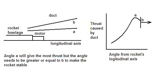
I used the same methods of numerical analysis in Excel to find angle b in the above picture; the smallest angle between the duct and the longitudinal axis to keep the rocket stable. All other dimensions for the duct are estimates. Here's the optimization program:
Spreadsheet that calculates Cg and Cp of model rocket (in .xls format)
When the file is opened it will show a graph that gives you the location of the center of gravity and the center of pressure against the end diameter of the duct. In order to visualize what the graph means just imagine that the y-axis is the longitudinal axis of the rocket. Then if you move that longitudinal axis from left to right, the intersection between the red and blue line with the axis gives you the location of the center of pressure and the center of gravity at the end diameter intersecting the axis. Since a rocket has to have a center of pressure below the center of gravity to be stable, the intersection of the red and blue lines tells you the minimum end diameter. The angle form the longitudinal axis (θ) and the end diameter are related by this equation:
tan θ = (end diameter - front diameter) / (2*length of duct)
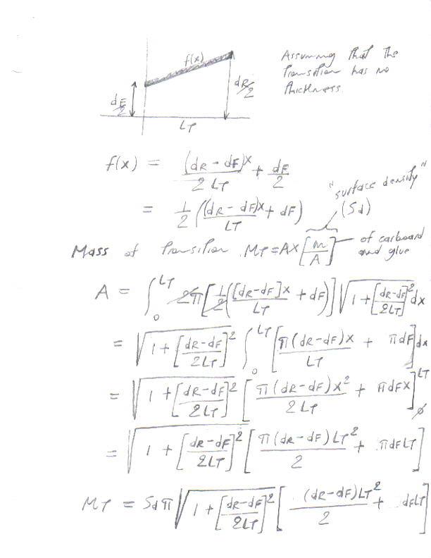
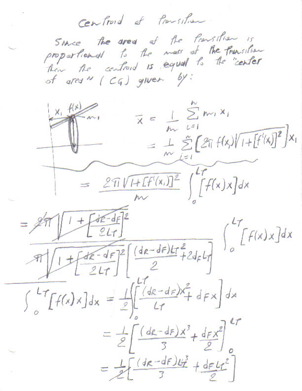
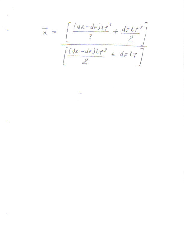
If you scroll to the left you will see three columns where the weights and locations of each component are shown. The graph is made by calculating the center of gravity and the center of pressure using Barrowman's equations for 59 different end diameters. For the original derivation of Barrowman's equations click here. To get the weight of the duct based on it's dimension and the "planar density" of the material used I came up with a formula based on this derivation; pg 1. To get the location of the center of gravity of the duct I came up with another formula based on these derivations; pg 1 and pg 2. As before the cells you can change based on your design are in red and all units are in grams and centimeters.